EVGA is a well-known American manufacturer of computer components. First of all, the company, of course, is known as a close partner of Nvidia in the release of video cards of the GeForce series. But over the time that has passed since its founding, other components and accessories have begun to be produced under this brand, and perhaps the most famous (after video cards) category of EVGA products are power supplies. The company provided us with several of its models for testing, and this time we will get acquainted with the “bronze” PSU 650 BQ . The manufacturer himself declares the BQ series as the perfect balance of quality, functionality and price.
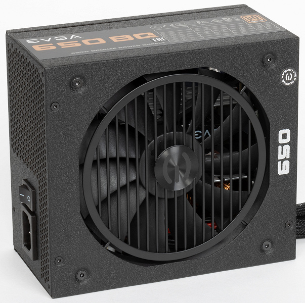
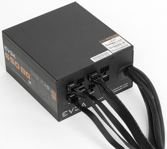
The length of the power supply case is about 165 mm, an additional 15-20 mm is required for the supply of wires, so during installation it is worth counting on an installation size of about 180 mm. Such models are usually not suitable for small-sized cases, but they will fit into almost any full-sized case without problems. The design of the PSU case is quite typical, except for the rather original ventilation grill, under which the fan is located. There is a special pad that prevents contact between the PSU grille and the case during installation.
The packaging of the power supply is a cardboard box of sufficient strength with matte printing. The design is dominated by shades of black and brown.
Characteristics
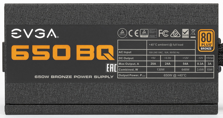
All the necessary parameters are indicated on the power supply case in full, for the power of the + 12VDC bus, the value of 648 W is declared. The ratio of +12VDC bus power to full power is 0.997, which is, of course, an excellent indicator.
The manufacturer notes that the power supply is capable of delivering maximum power at an ambient temperature of no higher than 40 ° C. For Russian climatic conditions, this should not be a problem. In general, the recommended operating temperature for computer power supplies is in the range from +10 to +50 ° C, but in the case of budget products, such a simplification is very common.
Wires and Connectors
| Connector name | Number of connectors | Notes |
|---|---|---|
| 24 pin Main Power Connector | one | collapsible |
| 4 pin 12V Power Connector | — | |
| 8 pin SSI Processor Connector | one | collapsible |
| 6 pin PCI-E 1.0 VGA Power Connector | — | |
| 8 pin PCI-E 2.0 VGA Power Connector | 4 | on two cords |
| 4 pin Peripheral Connector | 3 | ergonomic |
| 15 pin Serial ATA Connector | 7 | on two cords |
| 4 pin Floppy Drive Connector | one |
Length of wires to power connectors
Fixed wires:
- to the main ATX connector – 56 cm
- to processor socket 8 pin SSI – 62 cm
- to the first PCI-E 2.0 VGA Power Connector – 55 cm, plus another 15 cm to the second of the same connector
Removable wires:
- to the first PCI-E 2.0 VGA Power Connector – 55 cm, plus another 15 cm to the second of the same connector
- to the first SATA Power Connector – 50 cm, plus 15 cm to the second, another 15 cm to the third and another 15 cm to the fourth of the same connector
- to the first SATA Power Connector – 50 cm, plus 15 cm to the second and another 15 cm to the third of the same connector
- to the Peripheral Connector (“molex”) – 55 cm, plus 15 cm to the second and another 15 cm to the third of the same connector, plus another 15 cm to the FDD power connector
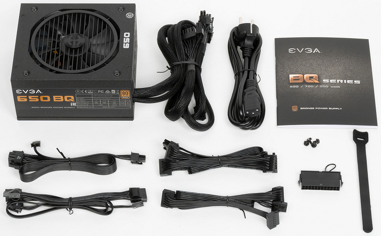
In this case, some of the wires are removable, and some are not. This option is quite convenient, since the main ATX connector and the processor power connector will be required in 100 percent of cases, and the video card power connectors will be needed in the vast majority of cases, since power supplies of such power imply the use of a discrete video card with additional power, although, of course, this is not necessary.
The length of the wires is sufficient for comfortable use in full tower and larger cases with a top-mounted power supply. In cases up to 55 cm high with a bottom-mounted power supply, the length of the wires should also be sufficient: up to the processor power connector – 62 cm. Thus, there should be no problems with most modern cases. True, taking into account the design of modern cases with advanced hidden wiring systems, the cord could well be made longer: say, from 70 cm, to ensure maximum convenience when assembling the system.
There are enough SATA Power connectors, but they are placed on two power cords. The connectors are straight, which is convenient in the case of drives placed on the back of the motherboard base.
On the positive side, it is worth noting the use of ribbon wires to the connectors, which increases ease of assembly. True, the wires to the main power connectors are made in the form of a conventional cord with a nylon braid, which is less convenient in terms of assembly and further operation.
Circuitry and cooling
The power supply is equipped with an active power factor corrector and has an extended supply voltage range from 100 to 240 volts. This ensures resistance to voltage drops in the mains below the standard values.
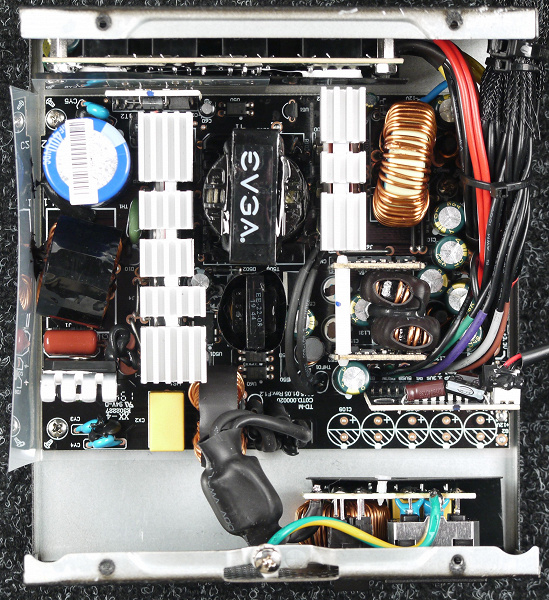
Semiconductor elements of high-voltage circuits are placed on one fairly large radiator with fins. The input diode assembly is also equipped with its own heatsink. The rectifier elements are located on a separate radiator. Independent sources of +3.3VDC and 5VDC are installed on daughter printed circuit boards located vertically, and, traditionally, they do not have additional heat sinks – this is quite typical for power supplies with active cooling.
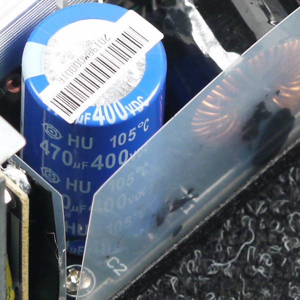
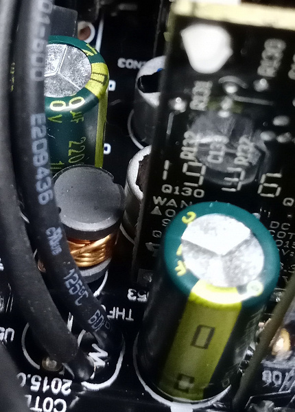
The capacitors in the power supply are mostly Teapo branded products, with the exception of the Hitachi high-voltage capacitor. A large number of polymer capacitors have also been installed. A set of capacitors, although budgetary, is far from the saddest for such a product.
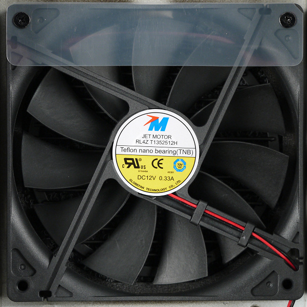
The fan is represented by the RL4Z T1352512H model manufactured by Jet Motor. The fan is based on a Teflon nano bearing, which is most likely a Teflon-coated (high slip) plain bearing on one of the elements, which in theory should increase the life of this assembly. In any case, the option is budgetary, and it is unlikely to be able to compete with a rolling bearing.
Measurement of electrical characteristics
Next, we turn to an instrumental study of the electrical characteristics of the power source using a multifunctional stand and other equipment.
The deviation of output voltages from the nominal value is color-coded as follows:
| Colour | Deviation range | Qualitative assessment |
|---|---|---|
| more than 5% | unsatisfactory | |
| +5% | bad | |
| +4% | satisfactorily | |
| +3% | well | |
| +2% | very good | |
| 1% or less | Great | |
| −2% | very good | |
| −3% | well | |
| −4% | satisfactorily | |
| −5% | bad | |
| more than 5% | unsatisfactory |
Working at maximum power
The first stage of testing is the operation of the power supply at maximum power for a long time. Such a test with confidence allows you to verify the performance of the PSU.
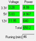
No noticeable problems were identified.
Cross load characteristic
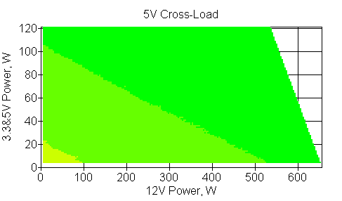
The next stage of instrumental testing is the construction of a cross-load characteristic (CNC) and its presentation on a quarter-plane, limited by the maximum power on the 3.3 & 5 V bus on the one hand (along the ordinate axis) and the maximum power on the 12 V bus on the other (along the abscissa axis). At each point, the measured voltage value is indicated by a color marker depending on the deviation from the nominal value.
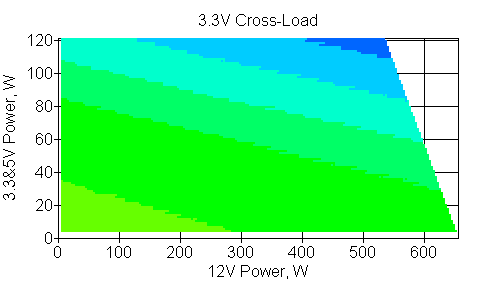
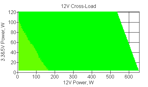
KNH allows us to determine what level of load can be considered acceptable, especially on the + 12VDC channel, for the instance under test. In this case, the deviations of the effective voltage values from the nominal value through the +12VDC channel are within 2% in the entire power range, which is an excellent result.
With a typical power distribution over the channels, deviations from the nominal value do not exceed 2% for the +3.3VDC channel, 3% for the +5VDC channel, and 2% for the +12VDC channel.
This PSU model is well suited for powerful modern systems due to the high practical load capacity of the + 12VDC channel.
load capacity
The following test is designed to determine the maximum power that can be supplied through the appropriate connectors with a normalized voltage deviation of 3 or 5 percent of nominal.
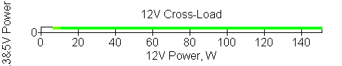
In the case of a video card with a single power connector, the maximum power through the +12VDC channel is at least 150 W with a deviation of 3%.
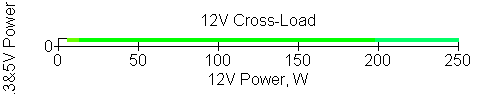
In the case of a video card with two power connectors, when using one power cord, the maximum power through the +12VDC channel is at least 250 W with a deviation within 3%.
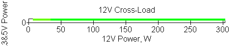
In the case of a video card with two power connectors, when using two power cords, the maximum power through the +12VDC channel is at least 300 W with a deviation within 3%, which allows you to use a very powerful video card.

When loaded through the processor power connector, the maximum power through the + 12VDC channel is about 250 W with a deviation of 3%. This allows you to use any desktop platform, having a tangible margin.

In the case of a motherboard, the maximum power per channel + 12VDC is at least 100 W with a deviation of no more than 3% from the nominal value. Since the board itself consumes within 10 W on this channel, high power may be required to power expansion cards – for example, for video cards without an additional power connector, which usually have a consumption of around 75 W. Thus, there shouldn’t be any problems.
Economy and efficiency
When evaluating the efficiency of a computer power supply, there are two ways to go. The first way is to evaluate the computer power supply as a separate electrical energy converter with a further attempt to minimize the resistance of the power transmission line from the PSU to the load (where the current and voltage at the PSU output are measured). To do this, the power supply is usually connected with all available connectors, which puts different power supplies in unequal conditions, since the set of connectors and the number of current-carrying wires are often different even for power supplies of the same power. Thus, although the results are correct for each specific power supply, in real conditions the data obtained is of little use, since in real conditions the power supply is connected to a limited number of connectors, and not all at once. Therefore, it seems logical to determine the efficiency (economics) of a computer power supply not only at fixed power values, including power distribution over channels, but also with a fixed set of connectors for each power value.
Representing the efficiency of a computer power supply in the form of an efficiency value (coefficient of performance) has its own traditions. First of all, efficiency is a coefficient determined by the ratio of the output and input powers of the power supply, that is, the efficiency shows the efficiency of converting electrical energy. For an ordinary user, this parameter will tell almost nothing, except that a higher efficiency seems to indicate a greater efficiency of the PSU and its higher quality. But efficiency has become a great marketing anchor, especially when combined with the 80Plus certification. However, from a practical point of view, efficiency does not have a noticeable effect on the functioning of the system unit: it does not increase performance, does not reduce noise or temperature inside the system unit. This is just a technical parameter, the level of which is mainly determined by the development of the industry at the current time and the cost of the product. For the user, maximizing efficiency results in an increase in the retail price.
On the other hand, sometimes you need to objectively evaluate the efficiency of a computer power supply. By efficiency, we mean the loss of power during the conversion of electricity and its transmission to end consumers. And to evaluate this efficiency is not needed, since you can use not the ratio of two values, but absolute values: power dissipation (the difference between the values u200bu200bof the input and output of the power supply), as well as the energy consumption of the power supply for a certain time (day, month, year etc.) when working with a constant load (power). This makes it easy to see the real difference in power consumption of specific PSU models and, if necessary, calculate the economic benefit of using more expensive power supplies.
Thus, at the output we get a parameter that is understandable to everyone – dissipated power, which is easily converted into kilowatt-hours (kWh), which is recorded by the electric energy meter. Multiplying the obtained value by the cost of a kilowatt-hour, we get the cost of electrical energy, provided that the system unit is operated around the clock throughout the year. Such an option, of course, is purely hypothetical, but it allows you to evaluate the difference between the cost of operating a computer with different power sources for a long period of time and draw conclusions about the economic feasibility of purchasing a particular PSU model. In real conditions, the calculated value can be achieved over a longer period – for example, from 3 years or more. If necessary, everyone can divide the obtained value by the desired coefficient, depending on the number of hours per day during which the system unit is operated in the specified mode in order to obtain electricity consumption for the year.
We decided to single out several typical options in terms of power and correlate them with the number of connectors that correspond to these options, that is, to bring the method of measuring efficiency as close as possible to the conditions that are achieved in a real system unit. At the same time, this will allow you to evaluate the efficiency of different power supplies in completely identical conditions.
| Load through connectors | 12VDC, W | 5VDC, W | 3.3VDC, W | Total power, W |
|---|---|---|---|---|
| main ATX, processor (12 V), SATA | 5 | 5 | 5 | fifteen |
| main ATX, processor (12 V), SATA | 80 | fifteen | 5 | 100 |
| main ATX, processor (12 V), SATA | 180 | fifteen | 5 | 200 |
| main ATX, processor (12V), 6-pin PCIe, SATA | 380 | fifteen | 5 | 400 |
| Main ATX, CPU (12V), 6-pin PCIe (1 cord with 2 connectors), SATA | 480 | fifteen | 5 | 500 |
| main ATX, processor (12 V), 6-pin PCIe (2 cords by 1 connector), SATA | 480 | fifteen | 5 | 500 |
| main ATX, processor (12V), 6-pin PCIe (2 cords of 2 connectors), SATA | 730 | fifteen | 5 | 750 |
The results are as follows:
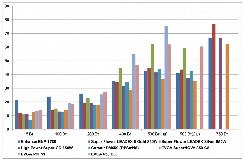
| Dissipated power, W | 15 W | 100 W | 200 W | 400 W | 500 W (1 cord) |
500 W (2 cords) |
750 W |
|---|---|---|---|---|---|---|---|
| Enhance ENP-1780 | 21.2 | 23.8 | 26.1 | 35.3 | 42.7 | 40.9 | 66.6 |
| Super Flower Leadex II Gold 850W | 12.1 | 14.1 | 19.2 | 34.5 | 45 | 43.7 | 76.7 |
| Super Flower Leadex Silver 650W | 10.9 | 15.1 | 22.8 | 45 | 62.5 | 59.2 | |
| High Power Super GD 850W | 11.3 | 13.1 | 19.2 | 32 | 41.6 | 37.3 | 66.7 |
| Corsair RM650 (RPS0118) | 7 | 12.5 | 17.7 | 34.5 | 44.3 | 42.5 | |
| EVGA SuperNova 850 G5 | 12.6 | fourteen | 17.9 | 29 | 36.7 | 35 | 62.4 |
| EVGA650N1 | 13.4 | nineteen | 25.5 | 55.3 | 75.6 | ||
| EVGA 650 BQ | 14.3 | 18.6 | 27.1 | 47.2 | 61.9 | 60.5 |
The higher the load power, the worse the efficiency of this model looks, but this is quite typical for budget solutions. In real conditions, it is unlikely that someone will load this power supply above 400 watts.
| Tue | |
| Enhance ENP-1780 | 106.4 |
| Super Flower Leadex II Gold 850W | 79.9 |
| Super Flower Leadex Silver 650W | 93.8 |
| High Power Super GD 850W | 75.6 |
| Corsair RM650 (RPS0118) | 71.7 |
| EVGA SuperNova 850 G5 | 73.5 |
| EVGA650N1 | 113.2 |
| EVGA 650 BQ | 107.2 |
At low and medium power, the consumption here is not the lowest, which is consistent with the level of the certificate and the positioning of the product as a whole.
| Computer energy consumption per year, kWh | 15 W | 100 W | 200 W | 400 W | 500 W (1 cord) |
500 W (2 cords) |
750 W |
|---|---|---|---|---|---|---|---|
| Enhance ENP-1780 | 317 | 1085 | 1981 | 3813 | 4754 | 4738 | 7153 |
| Super Flower Leadex II Gold 850W | 237 | 1000 | 1920 | 3806 | 4774 | 4763 | 7242 |
| Super Flower Leadex Silver 650W | 227 | 1008 | 1952 | 3898 | 4928 | 4899 | |
| High Power Super GD 850W | 230 | 991 | 1920 | 3784 | 4744 | 4707 | 7154 |
| Corsair RM650 (RPS0118) | 193 | 986 | 1907 | 3806 | 4768 | 4752 | |
| EVGA SuperNova 850 G5 | 242 | 999 | 1909 | 3758 | 4702 | 4687 | 7117 |
| EVGA650N1 | 249 | 1042 | 1975 | 3988 | 5042 | ||
| EVGA 650 BQ | 257 | 1039 | 1989 | 3918 | 4922 | 4910 |
Temperature regime
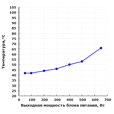
There are no special complaints about the temperature regime of capacitors in the PSU. Exceeding the value of 60 degrees was registered only at the maximum load power.
Acoustic ergonomics
In preparing this material, we used the following method for measuring the noise level of power supplies. The power supply is located on a flat surface with the fan up, above it at a distance of 0.35 m is placed the measuring microphone of the Octava 110A-Eco sound level meter, which measures the noise level. The power supply is loaded using a special stand that has a silent mode of operation. During the noise level measurement, the power supply is operated at constant power for 20 minutes, after which the noise level is measured.
Such a distance to the measurement object is the closest for the desktop placement of the system unit with the power supply installed. This method allows you to evaluate the noise level of the power supply in harsh environments in terms of a small distance from the noise source to the user. As the distance to the noise source increases and additional barriers appear that have good sound reflecting ability, the noise level at the control point will also decrease, which will lead to an improvement in acoustic ergonomics in general.
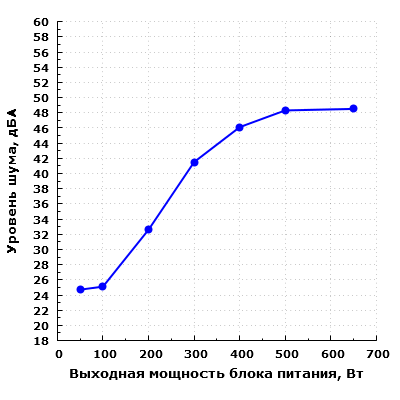
When operating in the range up to 100 W inclusive, the noise of the power supply is at a low level – less than 25 dBA from a distance of 0.35 m. When operating at a power of 200 W, the noise can be considered average for a residential area during the daytime. This level of noise is quite acceptable when working at a computer.
With a further increase in output power, the noise level increases markedly. At a load of 300 W, the noise of the power supply already exceeds the value of 40 dBA when placed on a desktop, that is, when the power supply is located in the near field in relation to the user. This noise level can be described as quite high. At maximum power, the noise of the power supply reaches 48 dBA, which is quite a lot.
Thus, in terms of acoustic ergonomics, this model provides comfort with an output power within 300 watts.
Moreover, judging by the fact that the temperature increases when the load rises from 500 to 650 W, and the noise does not change, the fan is installed here without a sufficient margin for rotation speed.
We also evaluate the noise level of the power supply electronics, since in some cases it is a source of unwanted overtones. This stage of testing is carried out by determining the difference between the noise level in our laboratory with the power supply on and off. If the obtained value is within 5 dBA, there are no deviations in the acoustic properties of the PSU. With a difference of more than 10 dBA, as a rule, there are certain defects that can be heard from a distance of about half a meter. At this stage of measurements, the sound level meter microphone is located at a distance of about 40 mm from the upper plane of the PSU, since it is very difficult to measure electronic noise at greater distances. The measurement is carried out in two modes: standby mode (STB, or Stand by) and when the PSU is working on the load, but with the fan forcedly stopped.
In standby mode, electronic noise is almost completely absent. On the whole, the noise of the electronics can be considered satisfactory: the excess of background noise was no more than 3.8 dBA at a power of 50 W.
Consumer qualities
The consumer qualities of the EVGA 650 BQ are above average if we consider the use of this model in a home system that uses typical components.
The acoustic ergonomics of the PSU is not the most outstanding, with a load of 300 W it already makes quite a lot of noise. But in real conditions, components with such consumption will themselves emit significant noise. At the same time, in idle mode and low load (up to 100 W), the PSU is really quiet.
The length of the wires at the PSU is quite sufficient for modern mid-budget cases.
We note the high load capacity of the platform via the +12VDC channel, as well as a large number of connectors and good efficiency. Our testing did not reveal significant shortcomings.
Results
The EVGA 650 BQ is a pretty solid mid-ranger, albeit with some nuances. In particular, I would like the fan to be on a bearing with a longer service life.
The technical and operational characteristics of EVGA 650 BQ are at the average level, which is facilitated by the high load capacity of the +12VDC channel, relatively high efficiency, moderate thermal load. But here they saved money on capacitors, it would be calmer to see the products of Japanese companies. On the other hand, this is still a budget product, and you need to save at least something when creating it.
For lovers of silence, this model is most likely not suitable, but for an inexpensive gaming system unit, the option is quite good, since there are no special complaints about the electrical characteristics, and in idle mode, the noise is low. The gameplay itself is usually accompanied by rather loud sounds of gunshots, explosions, clanging of metal, screeching tires, etc.


